1
General Discussion / How to use BLE4.0 Shield
« on: August 27, 2016, 04:56:39 AM »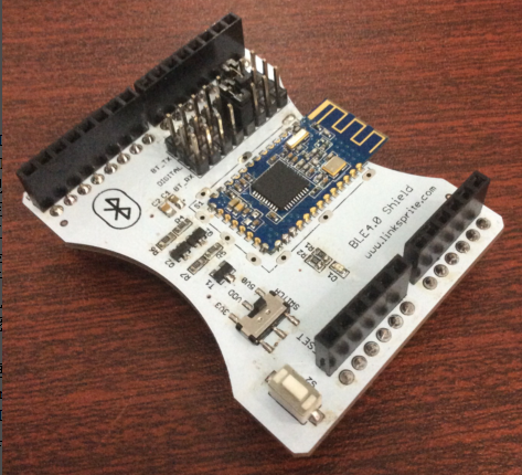
BLE4.0 Shield is an arduino shield which based on TICC2541. The AT instruction set integrated by BLE4.0 module is simple and effective to use, and greatly shorten your developing period. Based on the bluetooth standard specification, Bluetooth Low Energy (BLE) technology allows BLE4.0 to further reduce peak power to half, comparing with traditional Bluetooth devices. The single-mode chip of Blue tooth4.0 (BLE) enables to work for a long time (up to several months even years), powered by single button battery. Instead, traditional Bluetooth technology generally asks for at least two AA batteries, meanwhile at most works for several days or weeks. The main disadvantage of previous blue tooth version is extremely low startup speed. For example, Blue tooth 2.1 spends 4s to startup, but it’s only takes 3 ms for Blue tooth 4.0 to startup. If comparing Blue tooth 2.1 to a basic “feature phone”, then, Blue tooth 4.0 would be a “smart phone”.
Hardware set up
Arduino UNO x1
BLE4.0 Shield x1
Test code
mobile device with Blue tooth 4.0 x1
Code: [Select]
#include <SoftwareSerial.h>
#define RxD 2
#define TxD 3
SoftwareSerial mySerial(RxD,TxD);
void setup()
{
pinMode(RxD, INPUT);
pinMode(TxD, OUTPUT);
mySerial.begin(9600); // the ble4.0 baud rate
Serial.begin(9600); // the terminal baud rate
}
void loop()
{
if(Serial.available())
{
mySerial.print((char)Serial.read());
}
if(mySerial.available())
{
Serial.print((char)mySerial.read());
}
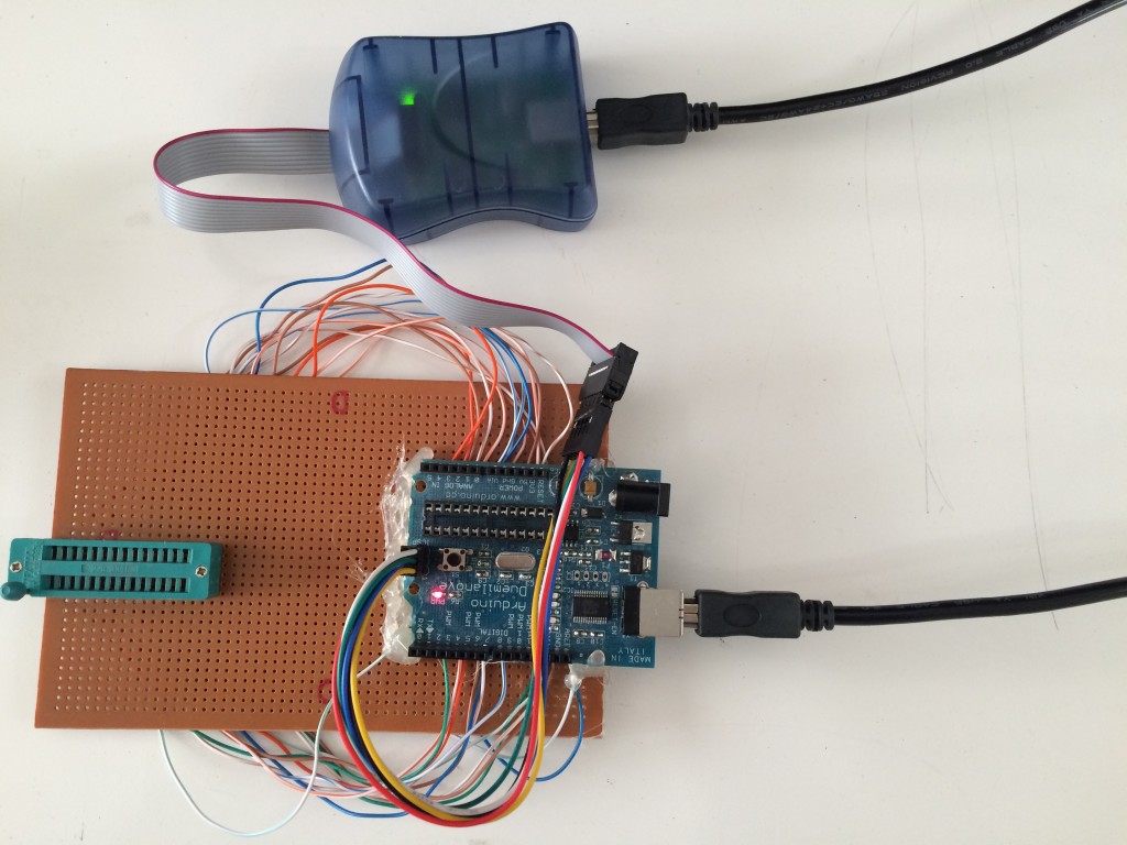
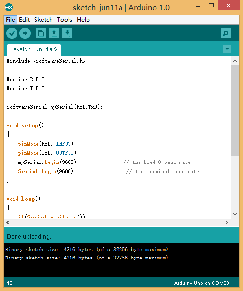
}(1) plug 0 shield in ArduinoUNO, and use a jumper cap to short circuit ( D2-BT_TX, D3-BT_RX), open ArduinoIDE and download test code: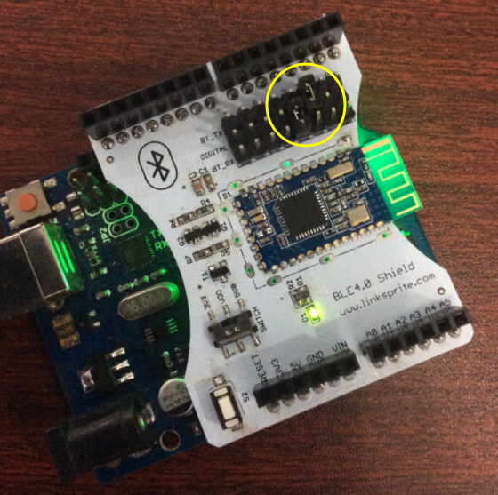
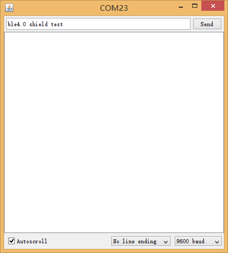
(2) open serial debugging window at right side of Arduino(baud rate 9600), send “AT” (attention: AT on this module should not add carriage return), we can see the module back to “OK”, then set the module to subordinate module:
check client-server mode: AT+ROLE? back: OK+GET:0 (“0” represent server mode, “1” represent client mode)
modify to server mode”AT+ROLE0″ back: OK+Set:0
check module name: AT+ROLE? back: OK+NAME:BLE_Shield
edit module name: AT+NAMExxx back: OK+Set:xxx
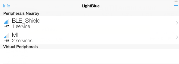
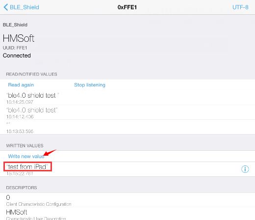
(3) install “lightblue” on mobile device, open software and search for Bluetooth devices, then connect to device named “BLE_Shield” and transfer data:
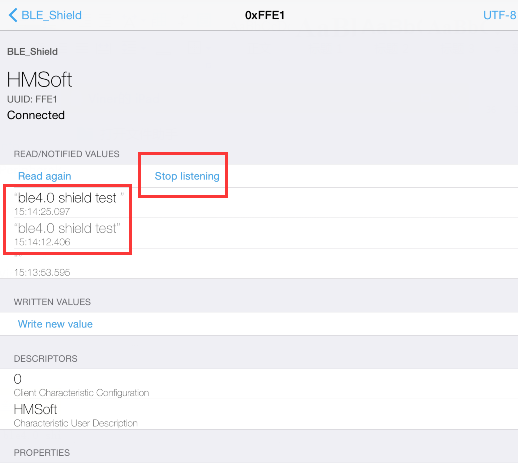
*click “listen for notifications” button monitor ( turn to “stop listening” after click it), receive data. Meanwhile, send test type string at ARduinoIDE serial port, and the data can be received:
*click ” Write new value”, send test type strings, and then you can receive type strings at ArduinoIDE sent by mobile device:

SCH: BLE4.0 Shield
AT: BLE4.0 AT Command
LED D1 :
When bluetooth ready to connection, LED blicking; when module have been connected device, LED continue bright.
press S1 ( for about 1s):
(1) module remains in sleeping mode:
module will return to normal mode, if open AT+NOTI, serial port will receive OK+WAKE
(2) module remains in connect mode:
module will initiate the request to disconnect
(3) module remains in standby mode:
module will restore to factory default setting.
SWITCH:
choose the GPIO level of micro-controller which connects with BLE4.0 is 3.3v or 5v.